RigBlocks
Last Updated: 08.18.2020
General
Profiles
Block profiles may have their settings changed at will. Profiles are simply presets.
General notes:
- Profiles are initially loaded at creation but they should be able to be safely loaded at
definestate - Distances are stored in
cm(maya's base unit) - Some settings are overridden by the buildProfile settings. For example some game buildProfiles will have endJoints off.
MASTER
Last Updated: 04.18.2019
The root rigBlock of our system. Not having one works for some setups but designed to be the root parent of any other rigBlock setup
Profiles
None
Settings
controlOffset
Float. This is a master only setting. This is a very important setting. This is our puppet's offset value for all of it's rigBlock shapes. It is used at many points during rig creation. The main effect is how far off of the proxy surface your control shapes will cast themselves for this master block controls as well as all sub modules.
addMotionJoint
Bool. This designates if our master will have a motion joint which is an extra root joint to move an animated skeleton around in game engine.
Define
The Master block skips the define state by default. The proper method for scaling the master block is to use the baseSize attribute to frame the object. Then rebuild the form state.
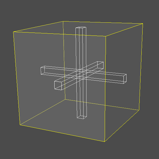
Form

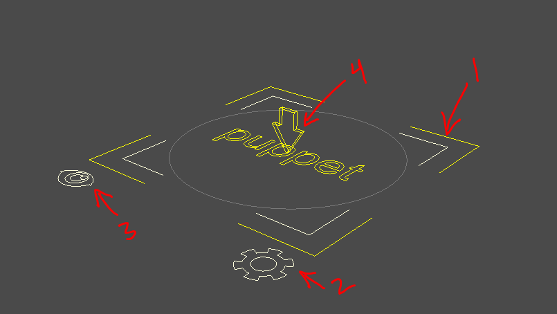
rigBlock[1] | The darker yellow interior curve is our master rigBlock's shape. Select it to get the dag.Bounding Box Visualization[2] | This represents the bounding box as our rigBlock understands it's own spaceCurve Offset Visualization[3] | This is to see how far off of our asset control curves will be set
Prerig
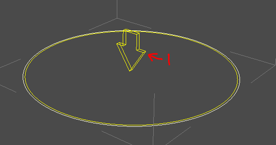
motionJoint Helper[1] | Arrow pointing down. The joint would be created at the dag of this prerig helpers.
Tip
Only builds when the addMotionJoint setting is True
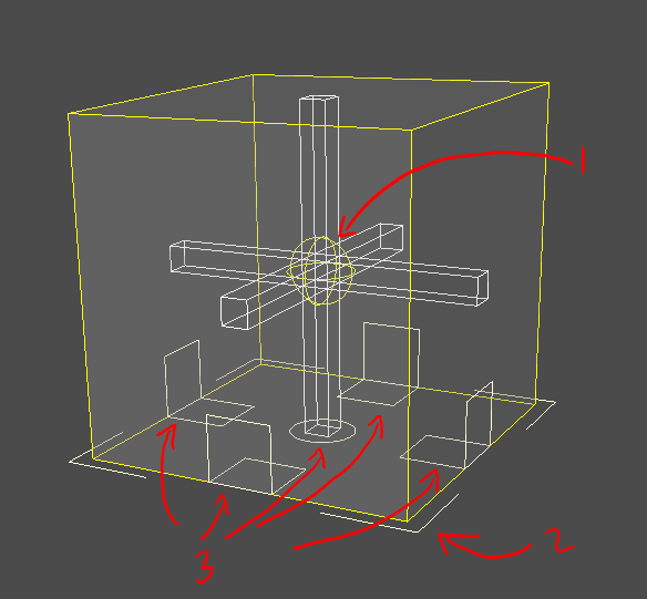
Rig
master
The master control [1] is the large square/rectangle with lighter offset curve and curve text of our character name
Attributes
visControl[bool] | visibility of the vis controlsettingsControl[bool] | visibility of the settings controlpivot_0... [enum] | visibility for each pivot as created by the setupspace[enum] | dynParent space toggle (when optioned)
settingsControl
Gear shape [2] at the base of our master. This is where we have some settings for our puppet. We plug in more items as we add sub modules.
Attributes
skeleton[enum] | off:lock:ongeo[enum] | off:lock:onproxy[enum] | off:lock:on
visControl
Eye shape [3] at the base of our master. Not really using this much now but it's a place to plug stuff.
Attributes
- rootMotionControl [bool] | visibility for the root motion control
rootMotion
Our same down arrow [4] as before. Used to move that joint.
Dag Structure
This will be more important to some of you than others. But our structure for a rigged asset begins with our master. Our master rigBlock creates a lot of nodes which you should have some understanding of in order to amend and modify your setups. All our subsequent rigBlocks will put their guts in this structure.

I'll lay them out and then discuss them briefly.
NAME_puppetNetwork(network | cgmRigPuppet[LINK THIS WHEN DONE])master(dag)rig(dag)noTransform(dag)parts(dag)worldSpaceObjects(dag)
geo(dagskeleton(dag)NAME_masterGroup(dag)NAME_anim(dag | cgmRigMaster[LINK THIS WHEN DONE])
control_displayLayer(display layer)main_displayLayer(display layer)all_animSet(objectSet)
PuppetNetwork
The puppetNetwork is a tagged mClass node of type cgmRigPuppet[LINK THIS WHEN DONE]. It is our core puppet wire source and target and has a large number of calls associated with it. We'll get more into that in the MRS Workshop on making your own module.
Master
The Main dag group in the outliner. This is our master null for the given puppet. We've named it "master" assuming any referencing will "tag" it such as "horse:master".
Groups/Nulls
Let's talk through our groups and what they're used for.
- rig | general group for the groups below it to keep that first level of children smaller
- noTransform | General noTransform group to stuff stuff when needed
- parts | each sub module added will add their own structure here. So for example, adding a spine that is rigged would add a spine null here and other dags at build time.
- worldSpaceObjects | collector for our dynamic parent group system to add it's dag targets to
- geo | Watch group for various calls where they'll be looking for geo. This is wired to the geo off/lock/on toggle so any children will get those settings
- skeleton | Null to put our bind skeleton. This is wired to the geo off/lock/on toggle so any children will get those settings
- masterGroup | Our master control's master group under which our rig structure will be that will be transformed by the main control.
Display Layers
Currently we build two display layers per asset.
Control| this should pretty much only affect controls so you can hide them on playbackMain| this is for the whole rig
Object Sets
There are a number of objects sets supported by MRS. Some are created initially. Some by post processes.
- all_animSet | Master anim set for puppet controls. Sub modules have their own sets added to this one
- bake_tdSet
- delete_tdSet
HANDLE
Last Updated: 04.18.2019
HANDLE | rigBlock for simple points of articulation
Profiles
Block profiles may have their settings changed at will. These are simply presets.
General notes:
- Profiles are initially loaded at creation but they should be able to be safely loaded at
definestate - Distances are stored in
cm(maya's base unit) - Some settings are overridden by the buildProfile settings. For example some game buildProfiles will have endJoints off.
Cube
basicShape| cubeproxyShape| cube
Sphere
basicShape| sphereproxyShape| sphere
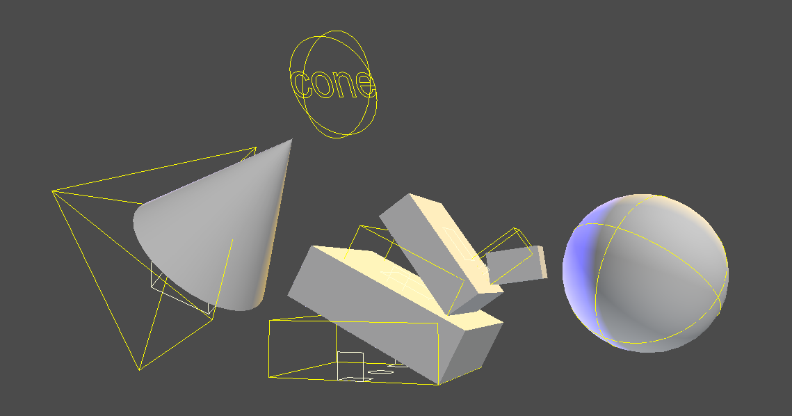
Cone
basicShape| pyramidproxyShape| cube
shapers4
proxyShape| shapersloftShape| squarenumShapers| 4numSubShapers| 0shapersAim| toEndloftSetup| default
shaperList
proxyShape| shapersloftShape| squarenumShapers| 4numSubShapers| 0shapersAim| toEndloftSetup| shaperListloftList| ['circle','square','wideDown','wideUp']
snapPoint
Snap points are special handles for prop joints for game work.
Note
After you build, this control's visiblity on the parent module's setting control. So if you add a snap point to the wrist you'll find an attribute on the arm's setting
Settings
Almost always located on our rigBlock dag
Special Calls
proxyGeo_getGroup
Makes sure we have a geo group. Can select it.
proxyGeo_add
Add proxy geo to the setup by duplication so as to leave the original in tact. Wiring it as needed.
proxyGeo_replace
Add proxy geo to the setup by duplication so as to leave the original in tact. Wiring it as needed. Remove what's there. What is removed will be parented to world and tagged with _REMOVED
UI
Has right click menu via mrsBuilder.
Report Group| Print the name of the groupAdd Selected| Add selected geo to the proxy geo setupReplace with Selected| Replace existing geo with selectedRemove Selected| Remove the selectedSelect Group| Select the geo group
Form
Shapes
Control Shape
In our case here it's the yellow cube. You can change that option but you'll need to retemplate to see it
ProxyShape
The geo cube is the proxy shape. You can change that option as well.
Attributes
On the rig block you'll find a proxy enum attr that will let you unlock the geo to manipulate it.
What are we looking for at this state?
- Shape | You want your template to generally match the look you're going for. If you're not working from a mesh and just an image plane really pay attention to your various angles.
Shared attributes
basicShape
enum | Kind of loft shape you want for the control.
circle:square:pyramid:semiSphere:sphere:cube
proxyShape
enum | Kind of loft shape you want for the proxy geo.
cube:sphere:cylinder:cone:torus:shapers
Shapers option give you our template setup to shape.
shapeDirection
enum | Which direction you want your basic and proxy shapes facing relative to your rigBlock dag
addScalePivot
bool | NOT IMPLEMENTED
loftSetup
enum | default:loftList
default| Single loft shape for each handleloftList| Specify each handle's loftShape via the loftList enum datList
loftList

loftList example
enum datList | Special datList verified at template state or loaded from initial profile
shapersAim
enum | toEnd:chain
toEnd| Each handle aims to the endchain| Each handle aims to the next handle
Prerig
What are we looking for at this state?
- Joint Handle | Place and orient the joint helper [1] where you want it
- Pivot Helper | OPTIONAL. When you have an addPivot setup you'll get this. You can use the main [2] to move them all and each pivot handle[3] to precisely place the points of banking
Skeleton
What are we looking for at this state?
- Joint orient | make sure they look like we expect
- Joint parent | make sure the root of your chain is going where you expect. When we get to the head for example, we wouldn't want that root of our neck to go to the pelvis unless we had a pretty atypical design.
hasJoint
bool | Do you want a joint
Rig
addAim
bool | Setup aim similar to the head setup
rotPivotPlace
enum | Define where you want the rotate pivot placement for your rig control.
Change Log
2019
February
- Documentation - UI, Special Calls
- Added loft setup to shape a handle item.
- Amended proxy mesh setup with this new option
- Added loftList setup. First block to receive
- Added ability to add custom geo
- UI for geo adding | add/replace/remove
January
- Docs | Initial pass
- Retool | Bringing this original prototype rigBlock up to snuff
- Added rigBlock handle
- Added new necessary dicts/attributes
- Initial testing
LIMB
Last Updated: 05.16.2019

LIMB | rigBlock targeted for hinged rig portions
Profiles
Block profiles may have their settings changed at will. These are simply presets.
General notes:
- Profiles are initially loaded at creation but they should be able to be safely loaded at
definestate - Distances are stored in
cm(maya's base unit) - Some settings are overridden by the buildProfile settings. For example some game buildProfiles will have endJoints off.
arm
finger
thumb
leg crab
leg plantigrade rear
leg digitgrade front
leg digitgrade rear
leg ungulate front
leg ungulate rear
leg unigrade
nub
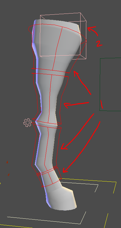
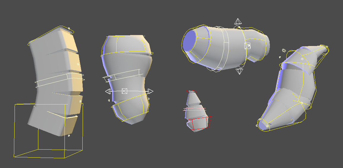
Define

Shapes
The locator form shape [1]. Select it to get the dag.
End Define Handle [2] | Defines the end point of our block. You can scale this and the bounding box scale visualization which change shape.
Attributes
- length
- width
- height
RP Define Handle [3] | Defines the rp vector for the block. This controls the rp Plane [6] visualization helper
Up Define Handle [4] | Defines up for our aim to the end.
Lever Define Handle [5] | Defines where the lever base position will be and the up vector for that setup. The up arrow helper on this control matters. If you form builds funky, check this.
Bounding Box Visualization [7] | bounding box representation of the baseSize
Settings
Form
When we form rigBlocks. Sometimes they have very different looks.How you decide you want your shaping control dictates what you do. As we talked about with `SEGMENT<#segment>`_ ).
See guide shape helpers for a breakdown on what the specific handles do.
There are a number of settings that affect our form.
Settings
- addCog
- attachPoint
- baseAim
- baseAim
- buildEnd
- ikBase
- ikEnd
- ikOrientToWOrld
- ikSetup
- loftDegree
- loftShape
- loftShapeStart/End
- loftSides
- loftSplit
- loftSetup
- numControls
- numJoints
- numShapers
- numSpacePivots
- numSubShapers
- proxyDirect
- proxyShape
- ribbonAim
- ribbonConnectBy
- ribbonParam
- scaleSetup
- settingsDirection
- settingsPlace
- spaceSwitch_direct
- squash
- squashExtraControl
- squashFactorMax
- squashFactorMin
- squashMeasure
- visMeasure
buildLeverBase
enum | The lever is what we call our base hinge setup with a clavicle for the first joint of a finger for example.
- dag | Turn on for structure to be created
- joint | If you want a joint there
The lever loft mesh will be extended when on.

buildBall
enum | Whether to add the ball. Adds a handle to our count.
buildToe
enum | Whether you want a toe or not. Adds a handle to our count.
Form Loft Mesh
This surface is imporant. It is used for proxy mesh creation and control curve casting. You can affect its shape via the loft handles and the settings to some degree.
Prerig
See guide shape helpers for a breakdown on what the specific handles do.
Workflow
Place the prehandles at the points of articulation you want.
Use builder tools:
Visualize | Rp Pos- See where the system things your knee or elbow are. If they're wrong check your rp vector handle.Snap to RP- Ensure the handle chain is on the same rotate plane
Skeleton
numRoll
int | A main value for how many roll joints per segment of joints.
rollCount
int/datList | A datList chain of attributes to set the roll count per segment of our LIMB. Currently set during the template state call.
Rig
- ikBase
- ikEnd
- ikOrientToWOrld
- ikSetup
- proxyDirect
- proxyShape
- ribbonAim
- ribbonConnectBy
- ribbonParam
- scaleSetup
- settingsDirection
- settingsPlace
- spaceSwitch_direct
- squash
- squashExtraControl
- squashFactorMax
- squashFactorMin
- squashMeasure
segmentMidIKControl
bool | This to setup an extra midIK control on the segment from one point of articulation to the other when you have roll joints.
ikEnd
enum | This makes it so the ball is setup as a reverse hinge to the ankle. It'll make more sense as we get into the material
ikRPAim
enum | This controls how our rp setup follows our chain. Note you can always change the space of the rp handle. This affects our main space driver.
default | Uses an up vector for the aim free | Vectorless aim following. We use this on the arm as we don't want the elbow to follow the wrist around as much as the knee generally.
buildLeverEnd
leg digigrade rear
bool | This makes it so the last section is setup as a reverse hinge to the ankle. We use this on our quad setups.
mainAxis
enum | This helps us counter flipping as it lets us figure out the twist axis by specifying the main. For example the main axis on a leg is out because it folds over the knee. Our arms because we usually orient them to be y going up through the shoulder would be up setup because that is the main axis of rotation to collapse the plane.
out | up |
Controls
The kinds of controls you see will depend on your rig options for the rigBlock. In our case we start with something like this.
Settings

leg digigrade rear
The settings [1] we've talked about on the spine. The gear is our standard settings shape when no cog is present
Note
Many of these attributes would not be on this control should we have a separate settings control
Attributes
- FKIK |
float| Blend between fk/ik mode. It controls that blend as well as the visibility of those controls. - visSub |
bool| Whether or not the subcontrols of this rig section are visible. In our case, we only have one. If we had used more joints than controls, we'd have more of these. - visRoot |
bool| Toggle visibility of the root control for the se - visDirect |
bool| Whether or not the per joint controls of this rig section are visible. By default they are cube curves. When the build option of proxyDirect is checked. The proxy mesh replaces those curves. - blendParam |
float| Determines how the joints follow the ribbon surface. Floating evenly or fixed to their attach point
IK End
Our main IK control [2-bottom]. The options and setup for our limb IK can be very different based on rigging options.
Attributes
- axisAim/Up |
enum| Settings for our aiming system. If you use raycast aiming or other systems these settings will be used per control. If no settings are found, the global defaults will be used. - pivot_0/pivot_1... |
enum| Same as discussed for master. - autoStretch |
enum| Stretch on our rp chain - lockMid |
enum| lock the mid to the rp handle - spinMid |
enum| twist the plane which guides the base follow for the rp handle - extendIK |
enum| When we have endLever on we get this attribute which controls how our ballRotation control orients - space |
enum| Setup by the dynParent System. orientTo would denote a point/Orient setup with orientTo setting the orient target and follow the position target

Attribute foot setup
Pivot Attributes - when we have a pivot helper we get extra options
- roll |
float| front to back edge - centerBank |
float| ... - centerRoll |
float| ... - spinFront |
float| ... - spinOuter |
float| ... - spinInner |
float| ... - spinBall |
float| ... - spinBack |
float| ... - bank |
float| Side to side edge
IK Base
This control IK Base [2-top] is for the start of the ik chain
Attributes
- axisAim/Up |
enum| Settings for our aiming system. If you use raycast aiming or other systems these settings will be used per control. If no settings are found, the global defaults will be used. - orientTo |
enum| Setup by the dynParent System. orientTo would denote a point/Orient setup with orientTo setting the orient target and follow the position target - follow |
enum| ...
RP Control
This rp control [3] controls our poleVector for our rp plane
Attributes
- axisAim/Up |
enum| Settings for our aiming system. If you use raycast aiming or other systems these settings will be used per control. If no settings are found, the global defaults will be used. - pivot_0/pivot_1... |
enum| Same as discussed for master. - follow |
enum| Setup by the dynParent System. Only follow would denote a point only setup
Segment Handles
The segment handles [4] control the ribbon for the segment joints. The number you see will be determined by our build options.
Attributes
- followRoot |
float| What the control follows. Be it the root or the blend frame.
Ball Rotation Control
The handle [5] acts as a reverse hinge for the foot. The buildLeverEnd is what makes this setup.
leg digigrade rear
Attributes
- axisAim/Up |
enum| Settings for our aiming system. If you use raycast aiming or other systems these settings will be used per control. If no settings are found, the global defaults will be used.
Note
The orient of this control is controlled by the extendIK attribute on the main ik control
Pivot Handles
Each of our pivots has a handle [6] for direct manipulation.
Note
Their visibility is controlled by settings.visSub.
FK Head
The FK head [3] is the default on head setups currently so it's what we see.
Attributes
- axisAim/Up |
enum| Settings for our aiming system. If you use raycast aiming or other systems these settings will be used per control. If no settings are found, the global defaults will be used.
Root Control
leg digigrade rear
The root control's [2] visibility is controlled by the settings. As we turned it on we can see it. It is a dag under which the rig is parented and as such legs you move the whole section of the rig when necessary.
Attributes
- axisAim/Up |
enum| Settings for our aiming system. If you use raycast aiming or other systems these settings will be used per control. If no settings are found, the global defaults will be used - space |
enum| OPTIONAL | Added when the spaceSwitch_direct option is on. Setup by the dynParent System. Space would denote a parent setup.
FK Controls
FK controls [1] are for direct rotation and movement
Attributes
- axisAim/Up |
enum| Settings for our aiming system. If you use raycast aiming or other systems these settings will be used per control. If no settings are found, the global defaults will be used
Direct Controls
We need to toggle an option to see some more:
- Settings
- visDirect | True
The direct controls' [1] visibility is controlled by the attribute we just changed. These are per joint controls for when the animator needs the highest fidelity of control.
On the neck we saw cubes. Because I already verified proxy on the leg. The cube shapes have been replaced by the proxy shape.
Attributes
- space |
enum| OPTIONAL | Added when the spaceSwitch_direct option is on. Setup by the dynParent System. Space would denote a parent setup.
visControl
On master. Remeber back on the master. The master settings has a new attribute registered with every module that builds that lets us see/interact with our rig guts.
Attributes
- R_FRNT_leg_limb_rig |
enum| toggle to hide/see but not touch/touch the rig guts
Known Issues
- Zero roll joint and multi roll joint on same limb | This causes some weirdness I'll resolve in the next sprint for unity mobile
Change Log
2019
April
- End rework |
buildEndreplacedhasEndJoint. Major rework to make more consistent - Form handle Seperation | rework so that the control/handle count is no longer tied to the form handles. This let users change their handle counts without having to reshape things.
- FK only building now
February
- Better define vectors
- Docs
- Updated some profiles
- Few image updates
January
- hadQuadSetup | This naming was confusing. Changed to buildLeverEnd as it's more useful than just quad setups and sometimes you don't want this on quads. Depreciating tipCombo out to use this instead.
- Docs | Initial pass
- Lever template | Worked on how lever template is setup to make it the sub loft curve setup more consistent
- FK cast dags | Added a dag cast setup for the fk shapes. A user was having a bug because we'd been using prerig handles and their end prerig handle was rotated very unexpectedly. May need to revisit to deal with more cases.
SEGMENT
Last Updated: 04.17.2019
SEGMENT | rigBlock targeted for flowing segments of joints
Profiles
Block profiles may have their settings changed at will. These are simply presets.
General notes:
- Profiles are initially loaded at creation but they should be able to be safely loaded at
definestate - Distances are stored in
cm(maya's base unit) - Some settings are overridden by the buildProfile settings. For example some game buildProfiles will have endJoints off.
Simple
Simple segment
attachPoint| endbaseVector| 0,1,0baseSize| 30,15,76ikBase| cubeikEnd| cubeikSetup| ribbonmainRotAxis| upnumControls| 4numShapers| 6numSubShapers| 3nameList| "start","end"segmentMidControl| TruesettingsPlace| start
Spine Up/Fwd
Our standard spine
- attachPoint | base
- base Vector | [up | 0,1,0 | fwd | 0,0,1]
- base Size | 30,15,76
- ikBase | hips
- ikEnd | tipMid
- ikSetup | ribbon
- mainRotAxis | up
- nameIter| "spine"
- nameList | "pelvis","chest"
- numControls | 4
- numShapers | 2
- numSubShapers | 3
- segmentMidControl | True
- settingsPlace | cog
Tail

attachPoint | base base Vector | 0,0,-1 base Size | 14,9,76 ikBase | simple ikEnd | tipBase ikSetup | ribbon nameIter| 'tail' nameList | 'tailBase','tailTip' numControls | 6 numShapers | 5 segmentMidControl | True settingsPlace | end
Tentacle
attachPoint| basebaseVector| 0,0,1baseSize| 14,9,76ikBase| simpleikEnd| tipBaseikSetup| splineloftList| 'wideDown','squircleDiamond','squircleDiamond','circle'mainRotAxis| upnameIter| 'tentacle'nameList| 'base','tip'numControls| 6numShapers| 4segmentMidControl| TruesettingsPlace| end
EarUp
In Testing
- attachPoint | end
- base Vector | 0,0,-1
- base Size | 10,10,20
- ikBase | simple
- ikEnd | tipBase
- ikSetup | ribbon
- nameIter| 'ear'
- nameList | 'earBase','earTip'
- numControls | 4
- numShapers | 2
- numSubShapers | 3
- segmentMidControl | True
- settingsPlace | end
Shared
- addCog
- attachPoint
- baseAim
- baseSize
- ikBase
- ikEnd
- ikOrientToWOrld
- ikSetup
- loftDegree
- loftShape
- loftSides
- loftSplit
- loftSetup
- numControls
- numJoints
- numShapers
- numSpacePivots
- numSubShapers
- proxyDirect
- proxyShape
- ribbonAim
- ribbonConnectBy
- ribbonParam
- scaleSetup
- settingsDirection
- settingsPlace
- spaceSwitch_direct
- squash
- squashExtraControl
- squashFactorMax
- squashFactorMin
- squashMeasure
- visMeasure
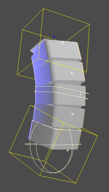
Define
Shapes
The locator form shape [1]. Select it to get the dag.
Up Define Handle [2] | Defines up for our aim to the end.
End Define Handle [3] | Defines the end point of our block. You can scale this and the bounding box scale visualization which change shape.
Attributes
- length
- width
- height
Form
Attributes
These attributes change what our template looks like.
- numShapers
- numSubShapers
- loftSetup
- loftList | If you have this option. Currently requires rebuild of template to change out
- loftDegree
- loftShape | Currently requires rebuild of template to change out
- loftSides
- loftSplit
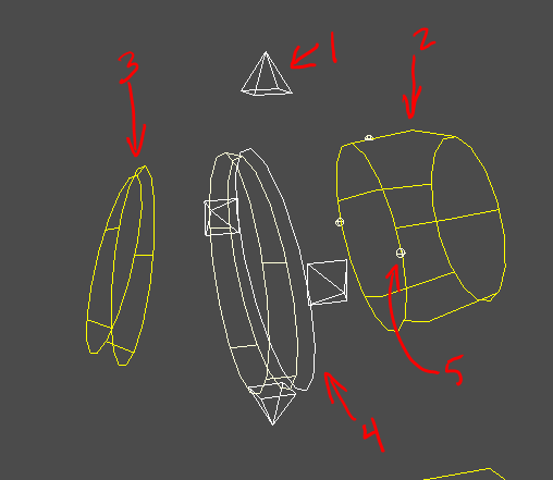
Shapes
When we template rigBlocks. Sometimes they have very different looks.How you decide you want your shaping control dictates what you do.
For example if you have a straight segment like a spine you'd probably just want something like this to have two major scale points and no need for mid articulation.
2 Shapers, 7 sub shapers = 9 loft handles
If you're doing a tail or something with breaks you probably want to have more handles and fewer sub shapers. The second setup ends with the same number of loft shapers but has a place to hinge things.
3 Shapers, 3 subshapers = 9 loft handles
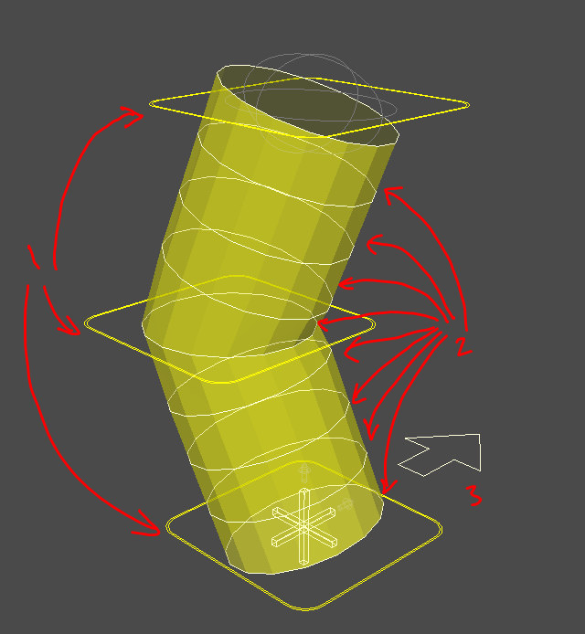
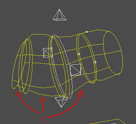
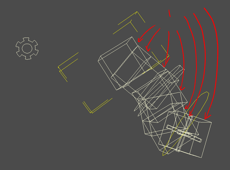
Form Handles
The dark rounded corner handles[1] (color will vary by side). They are used for big movements and scaling. Sub shaper handles are controlled by these.
Loft Handles
These are the actual curve handles [2] that our template loft runs through
You can change the cvs on these however that data isn't currently stored in our blockDat so rebuilding will wipe it
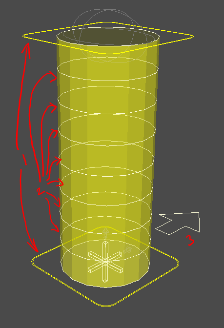
Orient Helper
This arrow shape [3] controls the 'up' of our segment root for rigBlock aiming and joint aiming.
Form Loft Mesh
This surface is imporant. It is used for proxy mesh creation and control curve casting. You can affect its shape via the loft handles and the settings to some degree.
Prerig
Attributes
- numShapers
- numSubshapers
segmentMidIKControl
bool. Whether to setup an extra midIK control on the segment
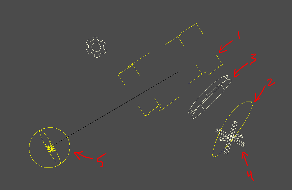
Shapes
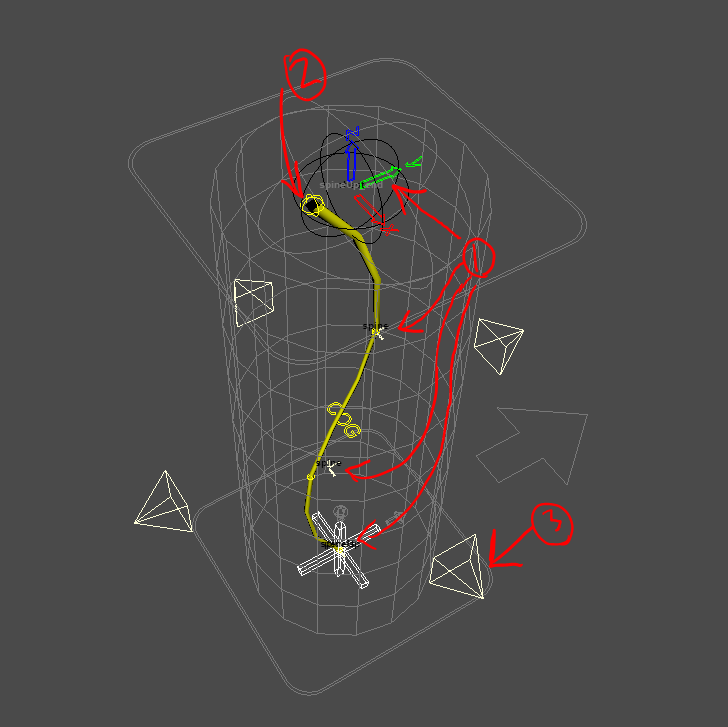
Prerig Handles
Axis shapes [1].
- These represent our points of articulation
- One per numControl count will be created
- The each have a joint handle with them
- The last one is colored by axis colors to differentiate as it is important. The IK handle during rigging will take the orientation of this handle. Pay attention to how it is rotated.
Joint Handles
These sphere shapes [2] are our handles to control our joint loft.
- The joint loft represents what our joint chain will be at the skeleton state
Joint Loft
The lofted surface running within our proxy loft is our joint loft. It represents what our joint chain will be.
- It is controlled by the joint handles
Note
We've toyed with the idea of per joint handles to exactly place roll joints but that would mean you'd have to rebuild the prerig every time you wanted to change the roll count. For now you can move them manually at skeleton state.
Rig
There's a lot of things happening when we rig.
- rigBlock | Our rigBlock has its
.templateattribute turned on so that it's easier to not inadvertently select it post rigging - Dag structure | created and setup for all our rig setup for both this block as well as others
- Shapes | Different nurbs control shapes are generated
- Rig wiring | The rig is wired so that we can get all the information we need once the rigBlock is removed from the scene. Remember it is a frame to build the rig and designed to be removed once we have our asset completed
- Dynparent setup | Based on our settings, the master will have our dynParent setup added as well as spacePivots for that system
Controls
The kinds of controls you see will depend on your rig options for the rigBlock. In our case we start with something like this.
Cog/Settings
The cog [1] we looked at previously. During the rig process our cog dag helper has a transform created at it, then the cog shape helper is shape parented to that new transform to make the control.
Because of our options, our cog is our settings control. This is an option. If you had had it off, you might see a gear instead.
Note
Many of these attributes would not be on this control should we have a separate settings control
Attributes
- FKIK |
float| Blend between fk/ik mode. It controls that blend as well as the visibility of those controls. - visSub |
bool| Whether or not the subcontrols of this rig section are visible. In our case, we only have one. If we had used more joints than controls, we'd have more of these. - visDirect |
bool| Whether or not the per joint controls of this rig section are visible. By default they are cube curves. When the build option of proxyDirect is checked. The proxy mesh replaces those curves. - axisAim/Up |
enum| Settings for our aiming system. If you use raycast aiming or other systems these settings will be used per control. If no settings are found, the global defaults will be used. - pivot_0/1 |
enum| Same as discussed for master. - blendParam |
float| Determines how the joints follow the ribbon surface. Floating evenly or fixed to their attach point - space |
enum| Setup by the dynParent System. Space would denote a parent setup.
Base/Mid/End IK
We are seeing the ik controls because we are in ik mode
- Base IK | Hip shape
[2]at the base of our spine - End IK | chest shape
[3] - Mid IK |
[4]
Attributes
- axisAim/Up |
enum| Settings for our aiming system. If you use raycast aiming or other systems these settings will be used per control. If no settings are found, the global defaults will be used. - pivot_0/1 |
enum| Same as discussed for master. - blendParam |
float| Determines how the joints follow the ribbon surface. Floating evenly or fixed to their attach point - space |
enum| Setup by the dynParent System. Space would denote a parent setup.
Segment Handles
We only see one [5] but as we mentioned. The number you see will be determined by our build options. When our control count matches our joint count we don't need an extra ribbon as we can use the main. When we have extra joints we have a separate ribbon which these controls would influence.
Attributes
- followRoot |
float| What the control follows. Be it the root or the blend frame.
FK Controls
If we turn on fk mode we'll see the fk controls.
Note the shapes hug our proxy we shaped during the template state.
Attributes
- axisAim/Up |
enum| Settings for our aiming system. If you use raycast aiming or other systems these settings will be used per control. If no settings are found, the global defaults will be used.
visControl (ON MASTER)
Remember back on the master. The master settings has a new attribute registered with every module that builds that lets us see/interact with our rig guts.
Attributes
- spineSegmentRig |
bool| toggle to hide/see but not touch/touch the rig guts
Dag Structure
For those that care about the rig structure
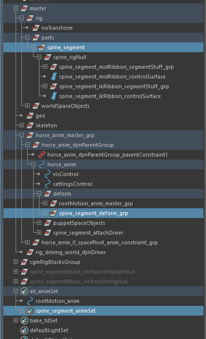
I'll lay them out and then discuss them briefly.
- spine_segment(dag- cgmRigModule)
- spine_rigNull(dag)
- spine_segment_deform_grp(dag)
- spine_segment_animSet(objectSet)
Module Dag/RigNull
The spine segment dag is a tagged mClass node of type cgmRigModule[LINK THIS WHEN DONE]. This is a special kind of dag that holds most pertinent information for the rig wiring.
- Non transforming dag | this dag is for non-transforming dags/nodes
Deform Group
We have a deform group that is placed under the master control deform group.
- Deforming nodes for the rig go here.
- Sometimes I have a separate constrain group under this
- Typically rig controls end up in here
Object Sets
Each rig Module gets its own animation objectSet to which all rig controls are registered
- spine_segment_animSet | Master anim set for puppet controls. Sub modules have their own sets added to this one
HEAD
Last Updated: 04.17.2019
HEAD | rigBlock targeted for heads | with or without necks
Profiles
Block profiles may have their settings changed at will. These are simply presets.
General notes:
- Profiles are initially loaded at creation but they should be able to be safely loaded at
definestate - Distances are stored in
cm(maya's base unit) - Some settings are overridden by the buildProfile settings. For example some game buildProfiles will have endJoints off.
Simple

Neckless head setup
attachPoint| endbaseSize| 15.2,23.2,19.7ikSetup| ribbonneckBuild| FalseneckControls| 0segmentMidIkControl| NA
neckLong
attachPoint| endbaseSize| 15.2,23.2,19.7ikSetup| ribbonneckBuild| TrueneckControls| 3segmentMidIkControl| True
neckShort
attachPoint| endikSetup| ribbonneckBuild| TrueneckJoints| 1neckControls| 1segmentMidIkControl| True
Special Calls
headGeo_getGroup
Makes sure we have a geo group. Can select it.
headGeo_add
Add proxy geo to the setup by duplication so as to leave the original in tact. Wiring it as needed.
headGeo_replace
Add proxy geo to the setup by duplication so as to leave the original in tact. Wiring it as needed. Remove what's there. What is removed will be parented to world and tagged with _REMOVED
headGeo_remove
Remove selected. What is removed will be parented to world and tagged with _REMOVED
UI
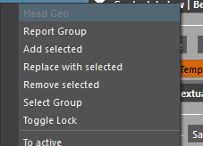
Has right click menu via mrsBuilder.
- Report Group | Print the name of the group
- Add Selected | Add selected geo to the proxy geo setup
- Replace with Selected | Replace existing geo with selected
- Remove Selected | Remove the selected
- Select Group | Select the geo group
- Head Geo Lock | Toggle the geo lock
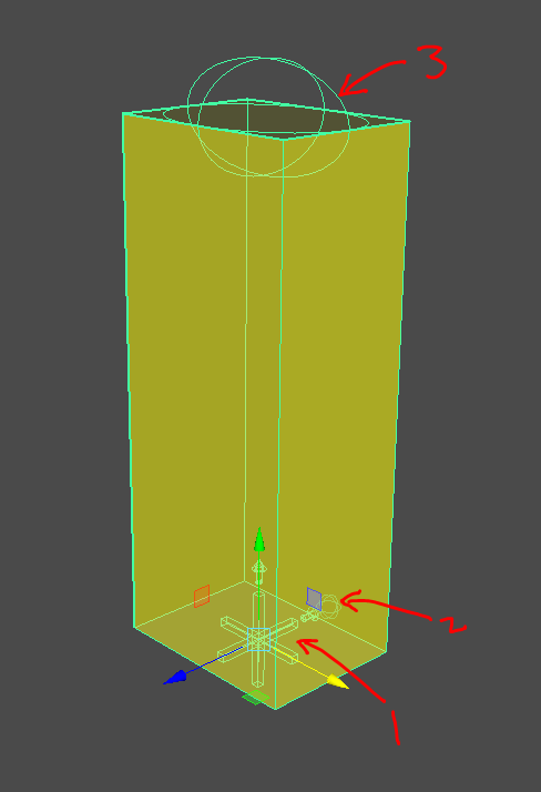
Define
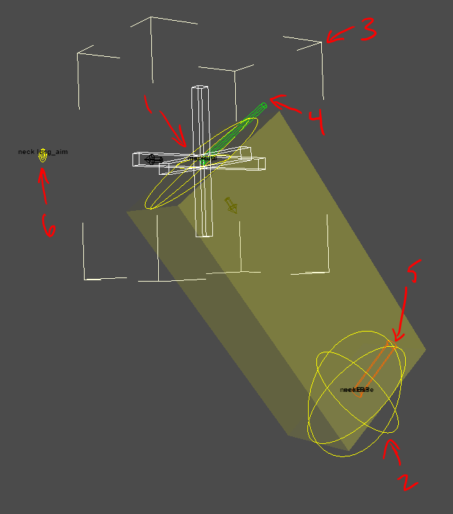
Settings
Shapes
The locator form shape [1]. Select it to get the dag.
End Define Handle [2] | Defines the end point of our block. You can scale this and the bounding box scale visualization which change shape.
Attributes
- length
- width
- height
Neck End Handle [2]
Defines the end point of our neck. You can scale this and the bounding box scale visualization which change shape.
Attributes
- length
- width
- height
Neck Up Handle [4]
Defines the upvector for the neck section. This controls the orientation of the neck bounding box visualization[6]
Neck RP Handle [5]
Defines the rp vector for the neck section.
Aim Handle [6]
Defines the aim point for the head. You'l get more finesse at the template state.
State Goals
What are we looking for at this state?
- Form | You're not worrying about the pivots here, just bounding box your frame
- Put the rigBlock in the middle of the head
- Use baseSize to approximately match the size of your head
- Move the neckBase handle to the base of the neck.
- Scale this volume to approximate your neck
- Aim | Place the aim handle where so that he aim vector is how you want aim forward on your head is.
- neckUp | Check your neckUp handle to make sure it's where you want it.
- neckRP | Ensure the neckRp handleis oriented how you want. Generally speaking the rp vector is through the main axis of rotation for that chain.
Form
See guide shape helpers for a breakdown on what the specific handles do.
State Goals
What are we looking for at this state?
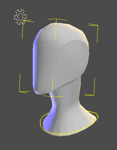
- Shape | You want your template to generally match the look you're going for. If you're not working from a mesh and just an image plane really pay attention to your various angles. I rotated my head geo up a little in my setup because it was a more natural orientation to me
- Head Handle | Make sure you like how it's shaped to your head. This shape will be used as our head control.
- Start Orient | Ensure the orient helper at the base of the neck is pointing where you want
- Head Orient | Make sure it's pointing where you want head forward to be. Our eventual headAim control will be eventually created along this vector
Settings
- addCog
- attachPoint
- baseAim
- baseSize
- ikBase
- ikEnd
- ikOrientToWOrld
- ikSetup
- loftDegree
- loftShape
- loftSides
- loftSplit
- loftSetup
- numControls
- numJoints
- numShapers
- numSpacePivots
- numSubShapers
- proxyShape
- ribbonAim
- ribbonConnectBy
- ribbonParam
- scaleSetup
- settingsDirection
- settingsPlace
- spaceSwitch_direct
- squash
- squashExtraControl
- squashFactorMax
- squashFactorMin
- squashMeasure

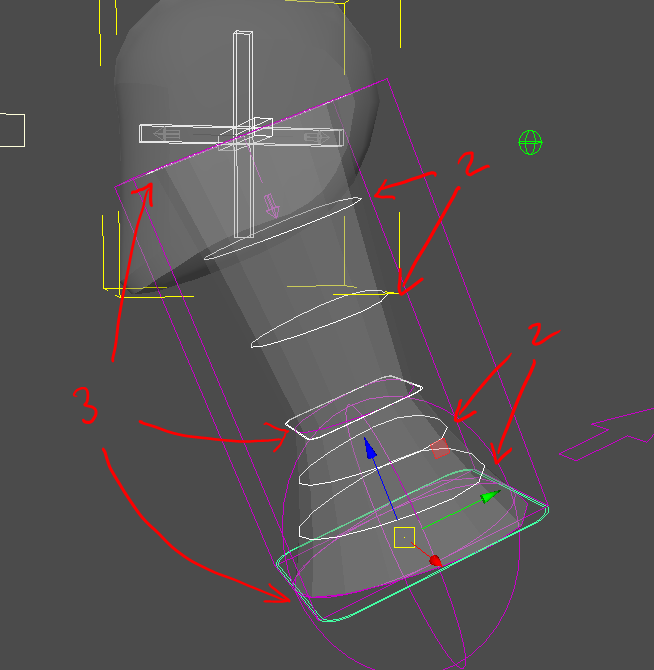
numShapers
int | numShapers | The number of shapers for a given section or block to help define it
int | numSubShapers | ...
This one has 3 shapers and 2 subShapers. The subShapers are split between the sub shapers.
Prerig
See guide shape helpers for a breakdown on what the specific handles do.
- One prerig handle created per control
State Goals
What are we looking for at this state?
Handles| Place the points of articulation where you want them. Use the jointLoft as a visual guide.
Skeleton
What are we looking for at this state?
- Joint orients | make sure they look like we expect
- Joint count | Make sure you have the number of joints you want to start iterating with
- Joint parent | make sure the root of your chain is going where you expect. When we get to the head for example, we wouldn't want that root of our neck to go to the pelvis unless we had a pretty atypical design.
Settings
neckJoints
int | How many neckJoints you want
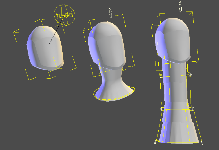
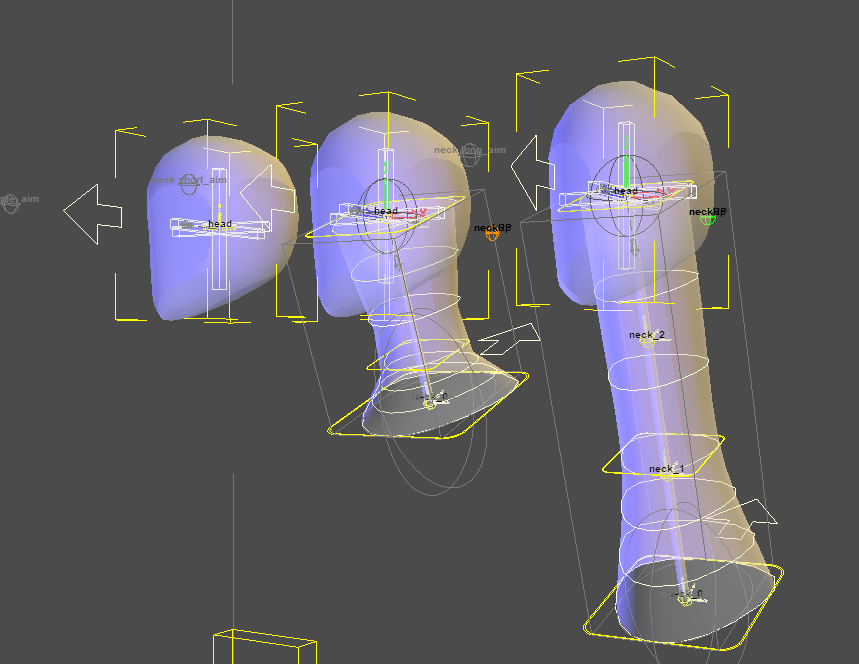
Rig

- Neckless head
- Single control neck, 1 neck joint
- Single control neck, 3 neck joints
- 4 control neck, 6 neck joints
Settings
segmentMidIKControl
bool | This to setup an extra midIK control on the segment from one point of articulation to the other when you have roll joints.
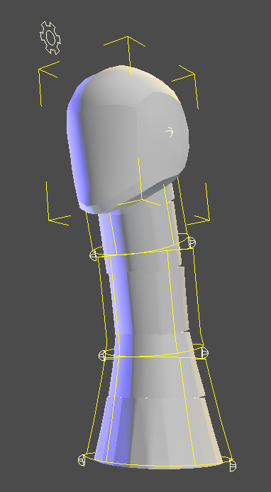
Controls

The kinds of controls you see will depend on your rig options for the rigBlock. In our case we start with something like this.
Settings
The settings [1] we've talked about on the spine. The gear is our standard settings shape when no cog is used.
Note
Many of these attributes would not be on this control should we have a separate settings control
Attributes
- FKIK |
float| Blend between fk/ik mode. It controls that blend as well as the visibility of those controls. - visSub |
bool| Whether or not the subcontrols of this rig section are visible. In our case, we only have one. If we had used more joints than controls, we'd have more of these. - visRoot |
bool| Toggle visibility of the root control for the se - visDirect |
bool| Whether or not the per joint controls of this rig section are visible. By default they are cube curves. When the build option of proxyDirect is checked. The proxy mesh replaces those curves. - blendParam |
float| Determines how the joints follow the ribbon surface. Floating evenly or fixed to their attach point - blendAim |
float| Blend the aim setup on or off. Also controls visibility of the aimControl
FK Neck
The FK head [3] is the default on head setups currently so it's what we see.
Attributes
- axisAim/Up |
enum| Settings for our aiming system. If you use raycast aiming or other systems these settings will be used per control. If no settings are found, the global defaults will be used.
Segment Handles
The segment handles [4] control the ribbon for the segment joints. The number you see will be determined by our build options.
Attributes
- followRoot |
float| What the control follows. Be it the root or the blend frame. - space |
enum| OPTIONAL | Added when thespaceSwitch_directoption is on. Setup by the dynParent System. Space would denote a parent setup.
We need to toggle a few options to see some more:
- Settings
blendAim| 1.0FKIK| 1.0visRoot| True
IK Controls
IK Head/IK Base
The IK head [1] and IK Base [2] are the ik control for the neck as well.
Attributes
* axisAim/Up | enum | Settings for our aiming system. If you use raycast aiming or other systems these settings will be used per control. If no settings are found, the global defaults will be used.
* orientTo | enum | Setup by the dynParent System. orientTo would denote a point/Orient setup with orientTo setting the orient target and follow the position target
* follow | enum | ...
Mid IK
The midIK [3] is only created when that option is selected.
Attributes
* axisAim/Up | enum | Settings for our aiming system. If you use raycast aiming or other systems these settings will be used per control. If no settings are found, the global defaults will be used.
Root Control
The root control's [4] visibility is controlled by the settings. As we turned it on we can see it. It is a dag under which the rig is parented and as such legs you move the whole section of the rig when necessary.
Attributes
- axisAim/Up |
enum| Settings for our aiming system. If you use raycast aiming or other systems these settings will be used per control. If no settings are found, the global defaults will be used. - space |
enum| OPTIONAL | Added when the spaceSwitch_direct option is on. Setup by the dynParent System. Space would denote a parent setup.
Head Aim Control
The root control's [5] visibility is blendAim turning on or off. This was added at a client request and is optional. When on, the head will aim at the target and rotating the blend aim on it's z axis (aliased to tilt) will tilt the head.
Attributes
- axisAim/Up |
enum| Settings for our aiming system. If you use raycast aiming or other systems these settings will be used per control. If no settings are found, the global defaults will be used.
Direct Controls
We need to toggle an option to see some more:
- Settings
visDirect| True
The direct controls's [1] visibility is controlled by the attribute we just changed. These are per joint controls for when the animator needs the highest fidelity of control.
The default shape for these is the cube you see above. However, when you create a proxy mesh these shapes are replaced by the proxy geo with a transparent shader set to them to make them selectable.
Attributes
- space |
enum| OPTIONAL | Added when the spaceSwitch_direct option is on. Setup by the dynParent System. Space would denote a parent setup.
visControl
On master. Rember back on the master. The master settings has a new attribute registered with every module that builds that lets us see/interact with our rig guts.
Attributes
- neckLongHeadRig |
bool| toggle to hide/see but not touch/touch the rig guts
Known Issues
None
Change Log
2019
April
- FK build | build with no ik now
February
- Docs updated | Some new images, added special calls and UI sections first pass
- Added RP vector handle for consistency
- LoftList implemented
January
- Reworked neck twist setup some for low counts.
- Aim head now will drive neck twist
- Docs | Initial pass
HAND
Last Updated: 04.18.2019

HAND - blockFrame for digits
This block is in very alpha state. This is our first blockFrame rigBlock . It's our digit handler or HAND for short.
Profiles
Block profiles may have their settings changed at will. These are simply presets.
General notes:
- Profiles are initially loaded at creation but they should be able to be safely loaded at
definestate - Distances are stored in
cm(maya's base unit) - Some settings are overridden by the buildProfile settings. For example some game buildProfiles will have endJoints off.
Human
numFinger| 4numThumbInner| 1numThumbOuter| 0fingerProfile| finger3definePose| relax
Toon
numFinger| 3numThumbInner| 1numThumbOuter| 0fingerProfile| finger3definePose| relax
HAND - blockFrame for digits
Paw
numFinger| 4numThumbInner| 0numThumbOuter| 0fingerProfile| finger1definePose| wide
Workflow
Roughly how hands are intended to be used.
- Place your arm or leg or whatever how you want it. When you're ready for your hand...
- Add a hand and set the blockParent to the thing it should follow and set the attachPoint
- Snap it to the end handle of the thing it should follow
- Size it using the base size and the handles
- Set your finger count and other options
- Verify your drivers
- Tweak those settings to shape and position
- Verify your subBlocks
- Push those subBlocks to template state
- Snap/Shape align those blocks
- Build and iterate to find a setup you like best
- When you're happy, mirror those subBlocks to the other side with or without a hand
Special Calls
verify_drivers
Builds the drivers from our eventual rigBlocks to be driven by the system
verify_subBlocks
Checks and/or rebuilds the rigBlocks driven by this rigBlock. Typically LIMB block fingers or thumbs.
subBlock_align
Call to snap/shape rig blocks to the blockFrame.
mBlockArg
str/mNode | What we want to process. If none, it does them all. If a rigBlock passed that has this as it's blockFrame, will use that one.
templateScale
enum | Whether to scale the template loft curves or not
UI
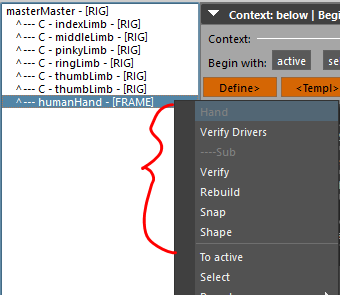
Has right click menu via mrsBuilder.
Verify Drivers| Rebuilds the drivers. If you change the finger count for example you'd want to do this- Sub
Verify| Make sure we have the driven rigBlocks we expectRebuild| Force a rebuild on the sub blocksSnap| Position and orient relevant handlesShape| Cast shape the loft curves as well as position and orient relevant handles
Define

Shapes
Bounding box
The size of this object is defined by the baseSize attr. When you define the block the define handles are spaced within this volume. So roughly sizing this to your hand will aid you in more quickly getting to what you want.
Define Handles
The little balls you see are to be used to roughly approximate the boundaries of the hand. The thumbs are more direct than the fingers which will sub split based on finger count.
Vector Handles
The Thumbs have vector handles which will be more clear once we have our drivers verified.
Settings
baseSize
float3 | We've used this before. The important thing here is that you change the size and the redefine to have the define handles lay themselves out in the volume represented.
definePose
enum | What positional layout do we want our initial define handles in our volume. The base vector for the thumbs are changed by this setting.
wide| Layed out on a plane as much as possiblerelax| Slightly rounded layout.
fingerProfile
enum | What LIMB profile do we want our sub blocks to use.
finger1| Single section fingerfinger2| Two section fingerfinger3| Three section finger. DEFAULT.thumb| Single section finger
State Goals
What are we looking for at this state?
- Position and orientation of the rigBlock
- Size using the base size
- Shape the general shape of the hand with the define handles
Drivers

This block as a special sub state when the drivers are. When you verify the drivers you'll see something like this (note, default material on)
Settings
There are a number of settings that affect our drivers.
numFinger
int | How many fingers do you want spread on our frame
numThumbInner
int | How many inner thumbs do you want. Inner thumb is what we have as humans. Only one supported for now.
thumbInner_0_scaleX/Y_X and finger_X_scaleX/Y_X
float datList | Current iteration on shaping the hand at this state. You have x/y scale control per driver per finger/thumb
paramFingerStart_X / paramFingerEnd_X
float datList | How you can slide the digits across the curves for more finese in placement
paramSplit_X
float datList | Where you want the breaks in the digits. Currently setup for 2 but plan on expanding in future.

SubBlocks
The idea of the blockFrame is it eventually creates the fingers/thumbs we need to make the actual hand work.
Using the ui, you can:
- Verify or rebuild subblocks
- Snap align them
- Shape align them
- Mirror to the other side
- Self mirror (why you would want to we're not sure but the tech was there from the facial stuff so).
Known Issues
- Param split setup for 2 and doesn't honor extra splits though it will still build fine
- You need to push mirror a couple of times when mirroring HAND rigBlocks.
BROW
Last Updated: 08.20.2020
Still ironing these out...
Define
Workflow
Place the block root between the brows
Use the
boundingBoxattr to kinda frame in the brow.- The bottom line should be under the typical brow line just above the ye
- The second line just frame in the eyebrow ridge
- The top should be the top of the forehead
Redefine it to push that new size to the define handles
Note
You can snap state handles to a selected mesh with the right click pop up in Builder
Shapes

Bounding box
Open Cube shape that changes with the boundingBox frame for the brow. Subsequent rebuilding of define after changing this will reposition the define handles within that volume.
Define Handles
The little balls you see are to be used to roughly frame in the brow.
- You can use the ui to snap handles to selected mesh
- Making your geo a live surface is also a good way to handle this
- Raycast handles is yet another option
Note
Size of define handles dictated by jointRadius
Form
Workflow
- See if you have enough handles to get the general shape before getting too far. If not, up the
formBrowNumorformForeheadNum - Place the form handles to conform the brow surface to your character
Note
You can snap state handles to a selected mesh with the right click pop up in Builder
Shapes

Surface
Just like most of our blocks, this one has a surface to help convey what the shape is we'll be deforming.
Form Handles
The little balls you see are to be used to control our surface.
formForeheadNum|int| Controls the number of form handle rows from brow ridge to peakformBrowNum|int| Controls the number of form handle rows from brow bottom to ridge
Note
Changing either of these options requires a form rebuild
Prerig
Workflow
- Check the prerig handle counts (joint and handles) to make sure you have as many as you want. If not, change and rebuild.
- Place anchors where you want them as these move the other controls
- Orient and tweak the control dag handles how you want your brow controls oriented
- Check the joint specfic control placement
- Check your depths with
conDirectOffset,controlOffsetandjointDepth
Note
You can aim prerig handles along the brow chains with the right click pop up in Builder
Settings
browType
enum | The ribbon for the brow. Whether you want that split or continuous
full| No center setupsplit| Control onlyside| NOT IMPLEMENTED
buildCenter
enum | What kind of center control do we want
none| No center setupdag| Control onlyjoint| Control and joint
conDirectOffset
float | Distance direct controls offset from surface
controlOffset
float | Distance main control shapes offset from surface
numBrowControls
int | Number of brow controls on each side. You want at least 2, otherwise just use a Handle
numBrowJoints
int | Number of brow joints on each side. We usually do between 3 and 5 depending on character and project needs
jointDepth
float | Distance joint dags and shapes inset from surface
Joint
Workflow
- Check where the joints are connected to on their parent especially if on a segment head to follow where you want.
- Make sure you have the joint count you want
Rig
Special Calls
uiFunc_snapStateHandles
Snap the state handles to a selected mesh
uiFunc_aimPreHandles Handles
Aim the brow pre handles along the chain
UI
Has right click menu via mrsBuilder.
Snap State Handles| Snap the state handles to a selected meshAim Pre Handles| Aim the brow pre handles along the chain
MUZZLE
Last Updated: 09.02.2020
Profiles
Still ironing these out...
Define
Workflow
Place the block root at the chin
Use the
boundingBoxattr to kinda frame in the muzzle.- The bottom line should be at the chin going back to about the ear
- The sides should frame in the jaw
- Depth shokd be to around the ear on a human face
- The top should be bridge of the nose
Redefine it to push that new size to the define handles
Note
You can snap state handles to a selected mesh with the right click pop up in Builder
Shapes

Bounding box
Open Cube shape that changes with the boundingBox frame for the muzzle. Subsequent rebuilding of define after changing this will reposition the define handles within that volume.
Define Handles
The little balls you see are to be used to roughly frame in the brow.
- You can use the ui to snap handles to selected mesh
- Making your geo a live surface is also a good way to handle this
- Raycast handles is yet another option
Note
Size of define handles dictated by jointRadius
Settings
boundingBox
float3 | This controls the bounding box volume
faceType
enum | What face profile for initial define setup. Still working through this one
default| Humanmuzzle| Canine/felinebeak| Noseless
jointRadius
float | At this point, this affects define handle size. It also affects some handle sizes later on
Form
Workflow
- See if you have enough handles to get the general shape before getting too far. If not, up the
formBrowNumorformForeheadNum - Place the form handles to conform the brow surface to your character
Note
You can snap state handles to a selected mesh with the right click pop up in Builder
Shapes

Surface
Just like most of our blocks, this one has a surface to help convey what the shape is we'll be deforming.
Form Handles
The little balls you see are to be used to control our surface.
Note
Changing options requires a form rebuild
Settings
numBridgeSplit
int | The number of handles rows that connect our bridges
numLipOverSplit
int | The number of handles rows for the lip bridge lofts
numLipUnderSplit
int | The number of handles rows for the lip bridge lofts
numLipShapersLwr
int | The number of handles for the various curves
numLoftBagU
int | U split
numLoftBridgeU
int | U split
numLoftBridgeV
int | V split
numLoftJawU
int | U split
numLoftJawV
int | V split
numLoftLipOverU
int | U split
numLoftLipUnderU
int | U split
numLoftLipU
int | U split
numLoftLipV
int | V split
numLoftNoseU
int | U split
numLoftNoseV
int | V split
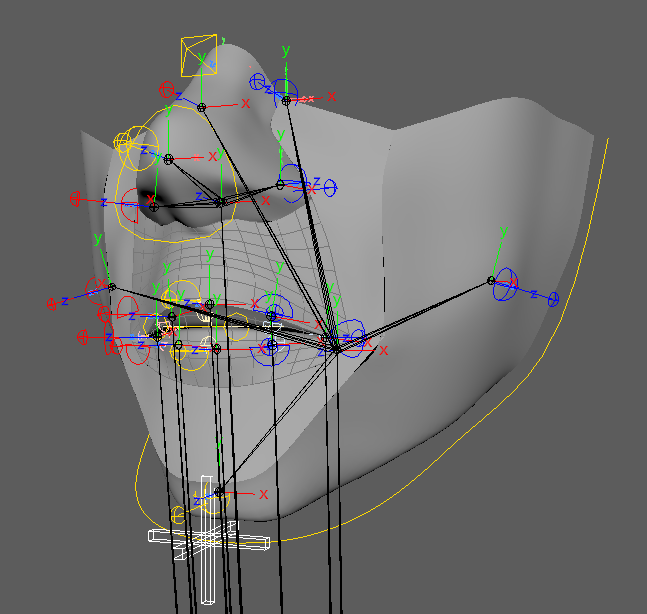
Prerig
Workflow
- Check the prerig handle counts (joint and handles) to make sure you have as many as you want. If not, change and rebuild.
- Place anchors where you want them as these move the other controls
- Orient and tweak the control dag handles how you want your brow controls oriented
- Check the joint specfic control placement
- Check your depths with
conDirectOffset,controlOffsetandjointDepth
Note
Pay attention to orients of your dag handles. They matter. The jaw and muzzle for example are vital.
Size
Size of controls is calcultated off of the base value which in this case is dictated by jointRadius.
- anchor |
base/ 1.5 - achor lips |
base/ 2.0 - direct |
base* .75
Settings
The muzzle has the most build option by far in terms of what's possible. We're trying to cover a wide range of setups and as such it's a long list. It's important to note:
Note
Many of these setup options must be on during prerig build and require a rebuild
bridgeSetup
enum | Not implemented yet
jawSetup
enum | Jaw setup option
none| No jaw setupsimple| Single joint jawslide| Not implemented yet
lipSetup
enum | Lip setup option.
Warning
This should always be default for now
none| No lip setupdefault| Regular lips
muzzleSetup
enum | Muzzle setup option
none| No setupdag| Dag only setupjoint| Setup with joint
numConLips
int | Number of handles across the lips from corner to corner
numJointsLipLwr
int | Number of joints across the lips from corner to corner
numJointsLipUpr
int | Number of joints across the lips from corner to corner
numJointsNoseTip
int | Number of joints in the nose tip. (Currently only support 1)
numJointsNostril
int | Number of joints in the nostril
numJointsTongue
int | Number of joints in the tongue. (Currently only support 1)
uprJawSetup
enum | Setup option
Warning
Not implemented yet
none| No setupsingle| Single joint setup
jointDepthLip
float | Separate offset for just the lip
Joint
Workflow
- Check where the joints are connected to on their parent especially if on a segment head to follow where you want.
- Make sure you have the joint count you want and controls everywhere
UI
Has right click menu via mrsBuilder.
Get define scale space dat| Dev tool for gettind data for profilesSnap State Handles to selected| Snap the state handles to a selected meshSeal Fix| Method to train the lip seal.
EYE
Last Updated: 09.05.2020
Profiles
clam
Single joint eye setup currently used on LBS Morphy kid.
nonSphereLid
Initially tackled non sphere setup in the summer of 2020. It works well enough for what we needed but needs more iteration. Currently you need to use surfaceSlide pupil or iris and as a joint to make this work.

Define
Workflow
Place the block root at the peak of the eye.
Change the base size to wrap the eye as best as possible. With nonspherical eyes you need to be especially careful.
When that is good, redefine the eye to get the lid handles to better positions.
Place the ends at the outer orb of the eye line and the starts at the inner corners. At the next step we get many more handles
Change the
jointRadiusto that the handles are nicely sized against the meshChange the
lidDepthto closely approximate the depht of the lids. This will be used at the next state to get better initial form.If you need to move the iris/pupil you can do it two ways:
- There is a little sphere control in from of the eye that the iris and pupil will follow
- Manually scale and move the pupil/iris
Note
You can snap state handles to a the eye orb with the right click pop up in Builder. Additionally making a face mesh live makes placing these handles much easier.
Shapes
Eye Orb
The eye orb is meant to match your eye geo no matter the shape.
Define Handles
The little balls you see are to be used to roughly frame in the lids. You won't see these if you don't have a lid setup eye.
- You can use the ui to snap handles to the eye orb
- Making your geo a live surface is also a good way to handle this
- Raycast handles is yet another option
The start handles are shaped as cylinders which will scale with the lidDepth attribute.
Note
Size of define handles is connected to jointRadius
Iris/Pipil
Note
These only build if you have iris/pupil
- Sphere in front of eye | This has a closest point setup connection to the iris/pupil shapes that follow below the surface of the eyeOrb
- Iris/Pupil | Conditional shapes that let you scale and shape the pupil/eye control shape.
irisDepthwill let you offset the follow on the surface together.
Settings
buildEyeOrb
bool | If we want an eye orb joint. A dag is assumed but we don't always want a skinning joint. If we do, turn it on.
irisBuild
enum | What kind of iris do we want
none| ...shape| ...visual shape for the proxyjoint| When we want an iris this is what we useblendshape| Not implemented but plan for a blendshape controlling the iris
irisDepth
float | How deep we want our template iris and pupil to ride under the orb surface
lidBuild
enum | Do we want a lid and if so what type.
none| Works great for spherical eyes.clam| Single joint setup. We're working on a new version of this. This may mean something different this fallfull| Full lid setup. Assumes more than one upr/lwr lid
Note
This must be on to get lid handles.
lidDepth
float | How far the lid is offset from the surface of the eye. Most important for the form build.
pupilBuild
enum | What kind of pupil do we want
none| ...shape| ...visual shape for the proxyjoint| When we want an pupil this is what we useblendshape| Not implemented but plan for a blendshape controlling the pupil
Form
Workflow
- If you don't have lids you can pretty much skip this step
- See if you have enough handles to get the general shape before getting too far. If not, up the
numLidLwr/UprShapersand rebuild - Place the form handles to conform the lid surface to your character
Note
If you have a mesh to work with. Just make the mesh live and snap. Remember the interior line of handles on the the lid already track the eyeball define surface
Shapes
Form Handles
The little balls you see are to be used to control our surface. numLidLwr/UprShapers controls how many data points you have.
Prerig
Workflow
- Check the prerig handle counts (joint and handles) to make sure you have as many as you want. If not, change and rebuild.
- Place anchors where you want them as these move the other controls
- Orient and tweak the control dag handles how you want your eye controls oriented
- Check the joint specfic control placement
- Move the scale pivot (if you have one)
- Check your depths with
conDirectOffset,controlOffsetandlidJointDepth
Note
Pay attention to orients of your dag handles.
Settings
The muzzle has the most build option by far in terms of what's possible. We're trying to cover a wide range of setups and as such it's a long list. It's important to note:
Note
Many of these setup options must be on during prerig build and require a rebuild
lidFanLwr/Upr
enum | If we want a fan joint setup
none| ...single| Single joint setup. This is something we're still working through.
lidJointDepth
float | How deep to sink the lid joints
numConLids
int | How many controls. 3 is the least you want for most full lids. With a non single joint setup. 3 is actually 5 with the corners automatically included.
numLidUpr/LwrJoints
int | How many joints per curve
paramMidLwr/Upr
float | Where to initially place single joint setups on their respective curves
prerigJointOrient
bool | Where
Joint

Workflow
- Check where the joints are connected to on their parent especially if on a segment head to follow where you want.
- Make sure you have the joint count you want and controls everywhere
Rig
Settings
Shared
highlightSetup
enum | Do we want a eye highlight control
none| ...simple| direct followsdk| sdk driverssurfaceSlide| highlight slides over the orb
ikSetup
bool | Do we want ik setup? Sometimes just a direct fk control is all we want.
irisAttach
enum | How we want the iris follow
parent| Works great for spherical eyes.surfaceAttach| First attempt for non spherical eyes. Attaches to the rig eye surface
pupilAttach
enum | How we want the pupil follow
parent| Works great for spherical eyes.surfaceAttach| First attempt for non spherical eyes. Attaches to the rig eye surface
lidAttach
enum | How we want the iris follow
aimJoint| Works great for spherical eyes.surfaceAttach| First attempt for non spherical eyes. Attaches to the rig eye surface
UI
Has right click menu via mrsBuilder.
Snap state handles| Dev tool for gettind data for profilesSnap selected| Snap the state handles to a selected meshAim Pre Handles| Aim the pre handles along the lid chains